Solved Figure shows the photodiode and its detection Circuit Diagram This circuit is designed to measure light intensity using a photodiode and a resistor to create a voltage divider, with the signal read by the Arduino Nano's A0 pin. A yellow LED is connected to the D2 pin, potentially serving as an indicator. The 9V battery powers the circuit, and the Arduino's code is yet to be implemented for specific
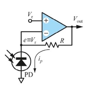
For the measurement of the transparency of differently structured glass I want to measure the change of lightintensity of a HeNe Laser shining through the glass, using a photodiode. I am using the following setup from a blog (Fotodiode am Transimpedanzverstärker - Blog von Familie Jörg): (Disclaimer: this is my first programming and electronics project, I do not fully understand all thats

Photodiode to measure light intensity Circuit Diagram
Hi, I want to use a BPW20RF photodiode and an operational amplifier. I am very new to all this and got confused how to set up the amplifier. When I directly plug in the photodiode in A0 and use a reference resistor of 30 Ohm, I get values of 0 to ~80 if I point directly with a flashlight on the sensor. Using an op-amp I want to increase this voltage to cover the whole level of 0 to 1023. Im

I'm using a RPI 3B and I'm reading photodiode outputs by passing them through an ADC (MCP3008). I used the setup and code in the link below as a reference. Except I've replaced the LDR with a photodiode, with the cathode of the photodiode connected to the resistor. I am also using an 8k ohm resistor instead. I'm trying to use a photodiode to measure light levels via an ADC on an ATMega168. I've got the microcontroller code working properly (measuring values on a pin and reporting it as an led brightness) but I'm having trouble getting the photodiode to report a voltage dependent on light levels.
Measuring light levels with a photodiode and an ADC Circuit Diagram
Yes, you can use multiple photodiodes in one circuit. This can be useful for detecting light from different directions or measuring light intensity at various points. When using multiple photodiodes, it is important to consider potential interference and shielding techniques to ensure accurate readings from each component. Conclusion. In this For DC light level my favorite (easy) circuit is to use a DMM with a uA current input, just measure the current the PD produces. The TIA above by fakemoustache is nice. I've used this too, V1 ~5-15V, R1 depends on the light level and area of PD. 10k to 100M ohm. simulate this circuit - Schematic created using CircuitLab Circuit for light intensity measurement Circuit for light intensity measurement. The circuit uses a p-n photodiode as the light sensor and a display driver IC LM3915 (IC1) to give a logarithmic current scale linearly with the incident light energy. The photodiode has a high-frequency response and fast switching speed of one nanosecond compared
