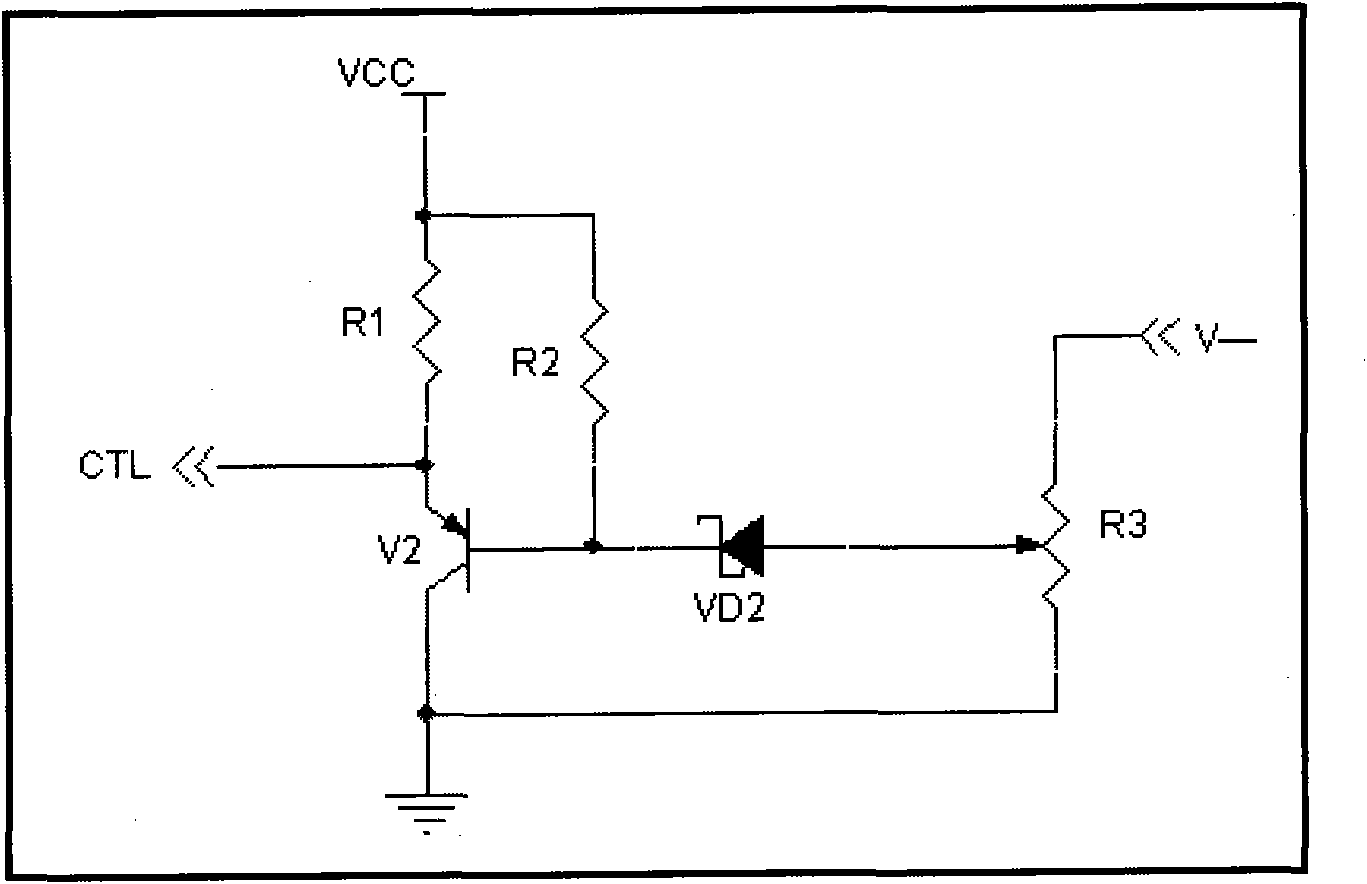
overvoltage protection Circuit Diagram The circuit diagram for the Overvoltage protection circuit is given below. First, we consider the working of the circuit when the power supply is working properly. In proper working state, the base terminal of transistor Q2 is high which causes that transistor to turn OFF. What is Overvoltage Protection? Overvoltage protection is a power supply feature that clamps the output or shuts down the power supply at higher voltage levels. Often, the voltage level must exceed the preset level for the protection to occur. An over-voltage protection circuit mainly prevents damage to the electronic elements of many power
Figure 1. A simplified illustration of a surge protection circuit used for intercepting a voltage surge. Normally, the electronics to be protected should continue to operate without interruption during an overvoltage. This requires the protective circuit to operate the circuit breaker (Q1 in Figure 1) in the linear range.
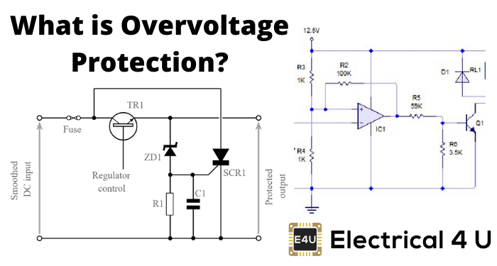
Voltage Protection Circuit ... Circuit Diagram
A user asks how to design a simple circuit to protect a device from overvoltage (more than 13V) using a zener diode and a MOSFET. See various answers and simulations with different approaches and components.
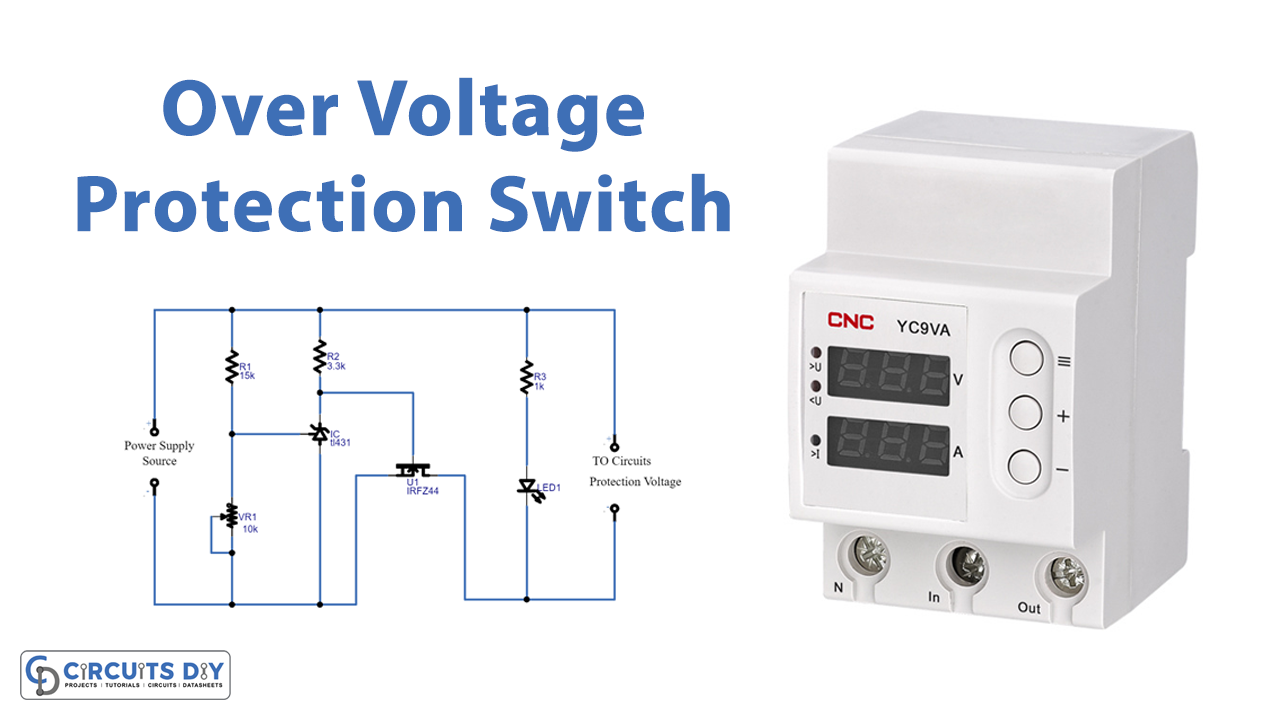
Learn how to protect your electronic devices from overvoltage, overcurrent, reverse polarity and back EMF with various circuits and components. See examples of crowbar, MOV, fuse, diode and SCR protection methods. This simple overvoltage protection circuit is easy to construct with few easily available components. To start this circuit you need to decide the regulating voltage range of zener diode based on load element and then connect two PNP transistors with specific voltage rage. In this circuit we have used two BC557 PNP transistors as a switch.
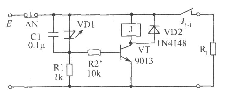
Overvoltage Protection Circuit Circuit Diagram
Previously Overvoltage protection circuit designed by using Zener diode and transistor. That circuit acts as regulator and cutoff switch for low voltage DC supply. This circuit uses SPDT Relay to control DC voltage load with respect to protecting from Overvoltage. (You can transform this circuit to control high voltage DC or AC load with