Lamps and Lights Page 22 Homemade Circuit Projects Circuit Diagram The most basic LED circuit can be made by sandwiching the legs around a coincell battery. This is also a good way to identify the positive and negative legs of the LED since it will only light up one way. In case you also need to add a switch, it goes between the battery's power wire and the LED positive side. Power up the circuit to
Indicator LED power circuits. There are multiple ways how you can safely connect an LED to mains voltage as an indicator and for todays purposes I'll stick to the very basic one. So the most basic way to connect an LED to the mains is through a resistor. However, some considerations need to be made before we actually connect it. For this second setup I decided to use the same LED, but up my power supply to the three AA batteries wired together which output 4.5V - enough power to burn out my 1.7V LED, so I would have to use a resistor. To figure out which resistor to use I used the formula: R = (V1 - V2) / I where: V1 = power supply voltage V2 = LED voltage
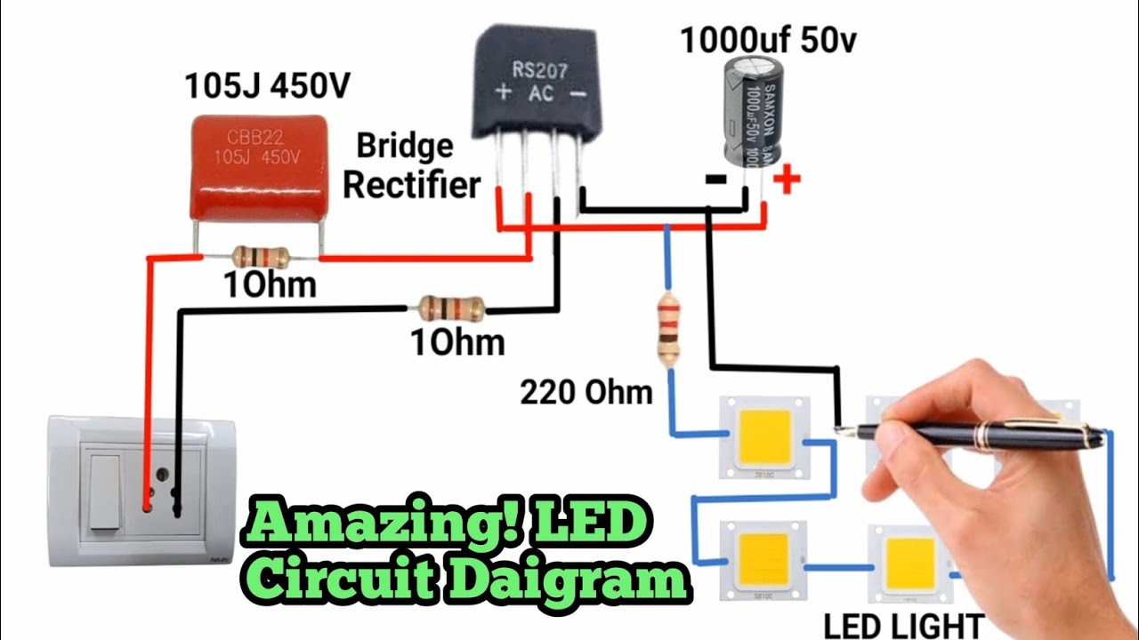
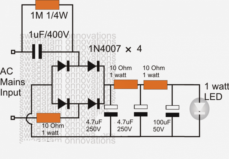
Simple Basic LED Circuit (How to Use LEDs) Circuit Diagram
I'm working on my first small electronics project; building a small LM317 based power supply. I've built the circuit as shown in the data sheet (black part of the circuit diagram below) on a perfboard. Now I wanted to add an LED to indicate if the switch is in on (bottom) or off (left) position. I added it to the circuit as shown below (red). This instructable will guide how to use LEDs and how to make simple basic LED circuits, which current limiting resistor to use for operating LEDs with 3V, 6V, 9V & 12V. For operating an LED with a 12V power supply or battery use minimum 560 ohms value resistor, or you can also use 1K maximum value.
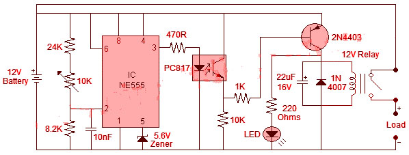
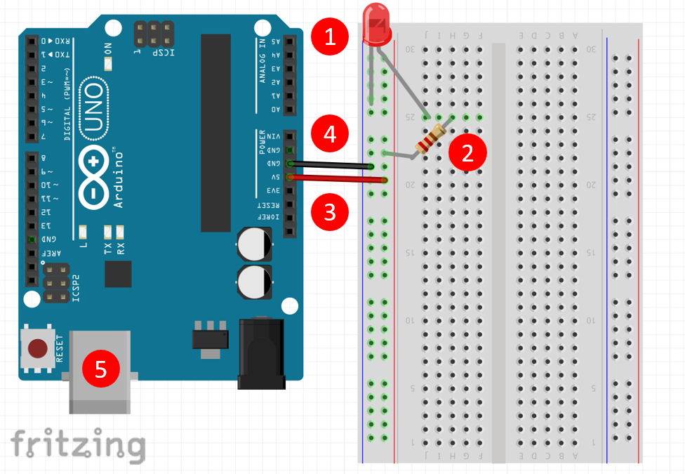
Create the Arduino LED circuit. For this circuit we will need: Arduino board. LED (any color, I will use red). Breadboard. 220 Ohm resistor (more info on the value later on). Some male to female wires. Build the circuit. Here is the circuit. How to build the circuit: First make sure that the Arduino is powered off (no USB cable plugged to In this post I have explained how to build a simple AC mains voltage indicator circuit which can be used to monitor the AC mains voltage levels. The IC LM324 Op-amps power an LED bargraph using the LEDs 1 to LED 7. The slider arm of potentiometer R16 supplies the op-amps with a programmable reference voltage.
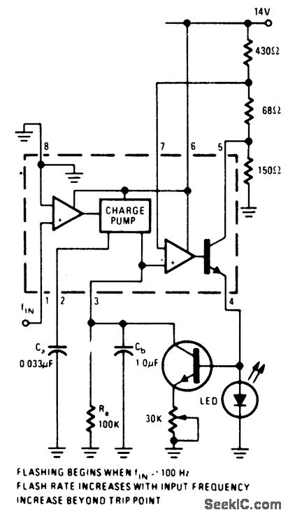
The Best Way to Make Indicator Lights with LEDs Circuit Diagram
Learning how to build a basic LED circuit is the perfect way to start exploring electronics!Table of Contents1. What is an LED Circuit?2. Understanding Polarity in an LED3. Standard LEDs - Used in indicators and low-power lighting. High-Power LEDs - Found in car headlights and flashlights.