Frequency Counter Circuits Everything You Need to Know Circuit Diagram The first frequency counter circuit concept discussed above involved the IC 4026 for the intended frequency measurements over 7 segment common cathode displays. Now I have explained a couple of more circuits using IC 74LS47 and IC 4033 and see how these ICs can be configured into specific frequency counter designs, as I have explained below.
Following is the code for Frequency Counter Circuit using 8051 Microcontroller. Frequency Counter Circuit Operation. Make the connections as per the circuit diagram and apply the Pulse generated by Arduino at Port 3 Pin P3.5, which is the Timer 1 Pin. As I have configured the Timer 1 as counter, using the TCON Bit TR1, I will be counting the
3 Simple Frequency Counter Circuits Discussed Circuit Diagram
To make calculations trivial using a 1 second gate time (T) gives a direct reading of frequency from the edge counter. Making a frequency counter for frequencies up to 65.536kHz is easy as the counters in a PIC chip can count up to 65535 without overflowing. Up to 65.535kHz all you do is wait for 1 second while the count accumulates, read the

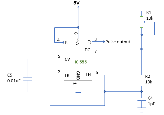
The most important part for the accuracy of the frequency counter is the time base setting circuit - crystal resonator X1 and capacitors C4 and C5. C4 and C5 values can be between 33pF and 62pF and the crystal frequency can be fine tuned with them. The input of the schematic is feed through a high speed comparator.
A frequency counter circuit project written in C using TMR1 and an 8 ... Circuit Diagram
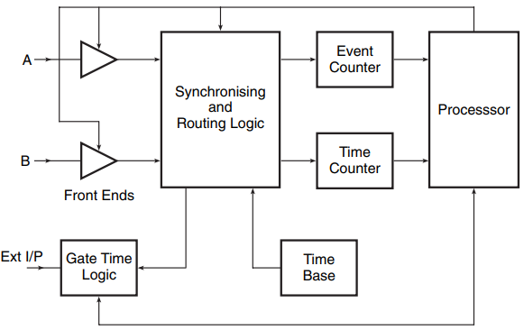
Frequency Counter: Schematics and C code for a PIC frequency counter circuit operating up to about 50MHz. This PIC frequency counter circuit uses a multiplexed seven segment display to provide 8 digits and uses timer 1 to count edges of the input signal and Timer 0 to count time.. It uses the simpler method of direct frequency measurement which means that the input event (for which you want to For the general theory of operation of this circuit and notes on frequency counting of this pic frequency counter click here. PIC frequency counter schematic using LCD and TMR0 and TMR1. (Click diagram to open a pdf.) PIC Frequency Counter: Hardware. The hardware is simple and the main blocks are shown in the diagram below.
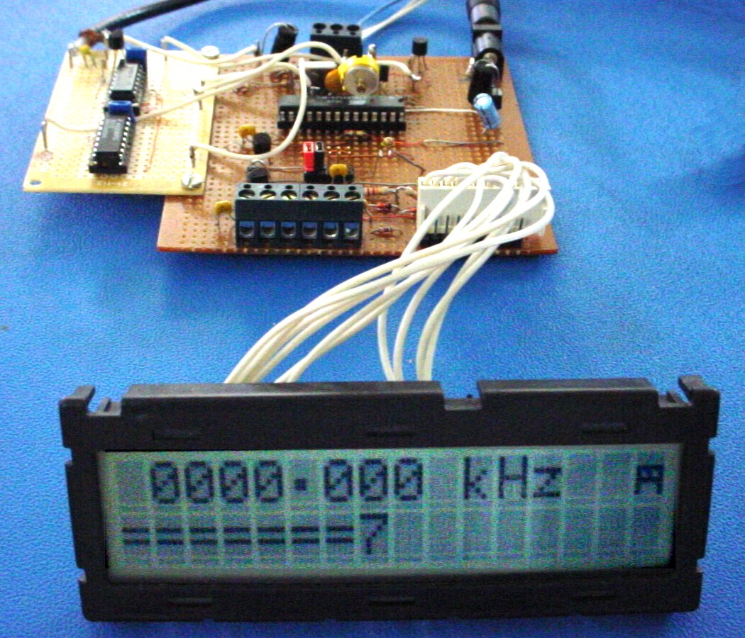
This document describes the construction of small frequency counter with a cheap PIC microcontroller and a few seven-segment LED digits. The main features of the frequency counter are: In the circuit, use PNP transistors for the CA display instead of NPN for T1 to drive the 5th digit, furthermore connect D1..D4 with reverse polarity, and